A more complex layout

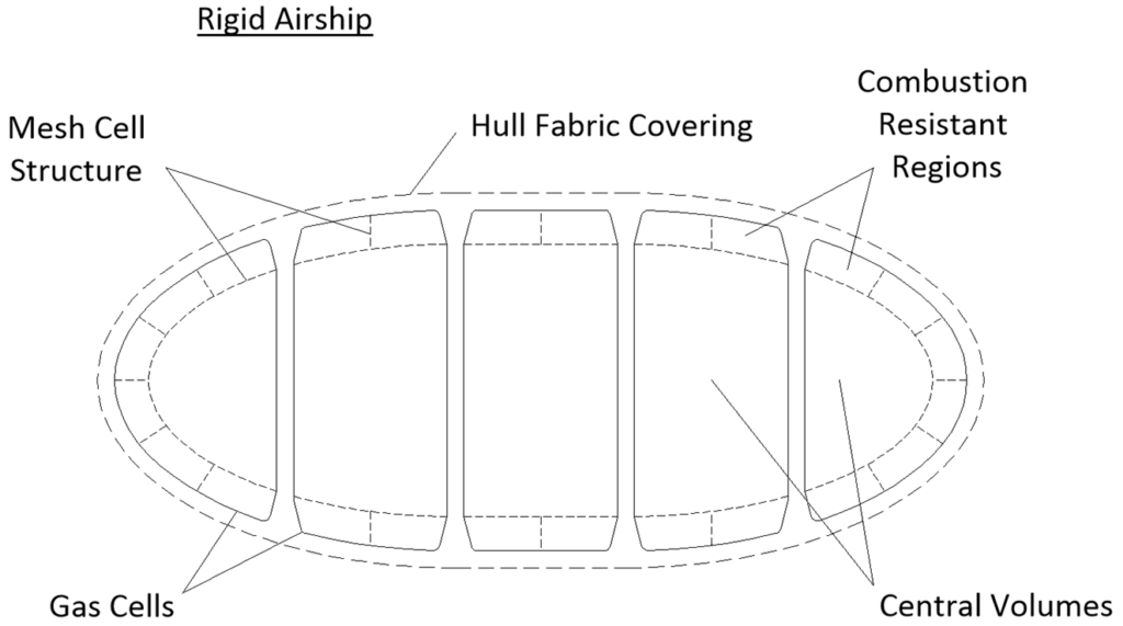
“Classic” layout for rigid airships comprise a number of gas cells filled with hydrogen supported within a rigid framework (not shown) forming the hull. The hull fabric covering keeps rain water out and forms a smooth surface to minimise drag.
The proposed flame arrester layout is also shown in the above figure. It provides a flame resistant region similar to the non-rigid airship already described, and will have similar weight and material costs.
However, there are more combustion risks to consider due to the gaps between the gas cells themselves and the gaps between gas cells, framework elements and hull fabric covering. Special attention is needed in the upper region where leaked hydrogen will rise and have its exit from the airship slowed by the hull fabric covering.
The main drivers of combustion
It is useful to understand some aspects of combustion in confined regions.
Combustion usually starts as deflagration, characterised by relatively low pressure waves (designers try to keep these within 0.5 to 1.0 bar overpressure) and subsonic flame speeds of less than 100 m/s. A combination of conditions can cause the deflagration flame to accelerate to the more destructive phases of deflagration to detonation transition (DDT) and detonation. The conditions for such flame acceleration include a hydrogen-air mixture with a high enough expansion ratio (such as a stoichiometric mixture), confined flow cross sectional area, turbulence from obstacles, nozzle type flow area changes and a sufficiently long flow path. Just a few of the above conditions acting together can cause DDT and detonation. Detonation is characterised by a shock wave and a maximum pressure of around 20 bar. A flame is coupled directly behind the shock wave propagating together at 1,400 m/s or higher. The DDT pressure can even reach 30 bar.
Combustion severity mitigation methods
Where combustion might occur airship designers should endeavour to prevent it. However, an airship design will be more robust if designers can prevent the more destructive DDT and detonation phases of an accidental combustion.
An overview of hydrogen-air combustion mitigation methods can be found in the Reference: HySafe BRHS Mitigation Measures, 2008.
Venting
Apart from internal gas cell combustion mitigation using the thin flame arrester innovation, other passive methods can be considered such as venting to minimise hydrogen build up between the gas cells themselves and the gaps between gas cells, framework elements and hull fabric covering. Again, the thin flame arrester innovation may have applications here.
Other Factors
Other combustion mitigation factors can be considered for non-rigid and rigid airships alike such as materials, air speed, valve positions and active fire suppression, especially in crew and passenger areas.

